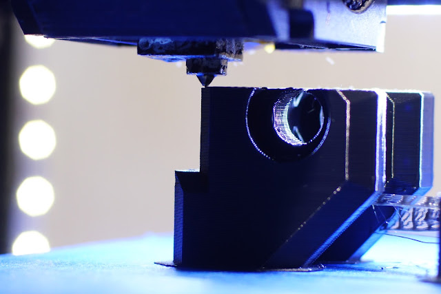
NUT TRAP
Plastic Widgets, when a piece of plastic makes all the difference, when the only thing standing between having a functional prototype is a small custom plastic widget...
and when your done printing, the fun continues with assembly. A number of machine axis are coming together, but who knows what the final config will look like. Yesterday I counted 5, today another 5. (and a few more in the next days)
Slowly the CNC Mill/Lathe's final form is taking shape, I think i've hit on a poor mans sherline configuration that could be close to how it will look (15 iterations in and still counting) but with the option to move things around. The Nema/Collet Chuck solution is a placeholder for the future upgrade, still waiting on some 16mm rails(they came so now the design forks into 2 seperate units), I'm keeping my eye on some extra large linear guides...so there will be a a few pieces of the puzzle coming together soon.
Now its a pity this nut trap isnt metal, but its the only piece of plastic in that axis, which will either be a cross-slide or a Z actuator for a router head (even if I can just etch out shapes in metal it would be useful). As this nut trap is for the setup with 8mm rails, I plan on making it shorter and seeing how it performs as a Router Plunger... I'll probably have a 12mm rods under the cross slide(or maybe not as the cross-slide/toolpost seems fine as it is), The Toolpost/Slide was pretty simple to convert to powered feed, I also added a thrust bearing behind the dial, not sure the 100oz nema17 will be good enough, so might have to redesign part for nema23.
The parts are stacking up and the center line is getting higher & higher, not sure where it will end up at the moment, but when I change to 12mm rods or another linear guide, i'll be looking for ways to keep things as low profile as I can get away with and the new 40mm wide x 670mm linear rail. It isn't the rail I wanted which has much beefier carriages, and ideally 3-400mm would be more that enough travel for a small lathe cant see me trying 400mm long work-piece anytime soon, i'll see how I get along with this rail and probably swap out later as this long one will make a great camera slider...I think I need a slider more than a lathe at the moment. hopefully slowly converting to custom metal parts, but thinking about the long uncharted path ahead makes me wonder about the time & cost for extra tooling... I think i'm in for a shock, making tools to make tools...
I've Lost count of the amount of different configurations...it's in a constant state of flux, merging with other machines, spawning new ones...
Tricky Little Problem Solved...I wanted to mount the motor to make belt tension adjustments easier, mulling over many #3dprinted parts but without modification to the metal plate
(a few more mounting holes would be great), but I was working with what I had, working out belt/center distance is a pain, there's probably a chart or calculator somewhere, the way things where going if I had printed something it was going to use a lot of plastic & still wouldnt be ideal...then bingo a solution without a printed part. As convenient as printed parts can be, I try not to use if I can get away with it, except for the exceptional part that screams Print Me! Like the little bearing holder in this pic, now I need another & the TR8 Nut Trap printing and this axis is done. I'll be moving the large pulley closer to the bearings. There is not much clearance under the large alu' block, not enough for a printed nut trap, and the only holes I have to work with are the ones on the side face so the nut trap will have to go there for now. Maybe in the future I'll alter the holes in this block to make it more useful, or merge the design of the plastic parts into a new custom saddle, so many options and while I want to arrive at a definitive arrangement, I also want to keep it as modular as possible, and trying to figure out which order for the 2 3 4 or 5 axis is just creating more permutations
Another Idea i'd like to follow is to flip the double rail setup 180 deg'
so the block rides on the rods & the rails are shielded from bits...
make a cover for the leadscrew, then add a t-slot plate, above the plate holding the twin rails for an extra long cross slide...or take the rails off the rods and add the lathe toolpost to the twin rails...and so it goes on...


Comments
Post a Comment